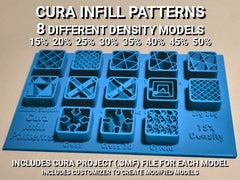
Cura Infill Patterns Display Models
This is a collection of Cura Infill Pattern Displays with models for 15%, 20%, 25%, 30%, 35%, 40%, 45%, and 50% infill density. Cura project files (.3mf) are included for each of the densities for easy printing setup. The project files have all of the necessary support blockers.
I saw ccarbs 20% density model (remix source) and liked the idea, but it would require 120 grams and take 9 hours 46 minutes to print with draft settings. Ain’t nobody got time for that! And the amount of material is even more of a concern.
So I designed my own model from scratch for 15% density, which is what I typically print at. And since it was easy to change the density on the model and the density in the print settings I made models and project files for each of the commonly used densities in case anyone wants one of those. These models require about 1/4 the material and print time as ccarbs original model.
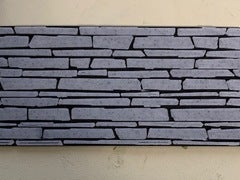
The first picture is a photo of a printed model but all others are rendered images that I made by converting the G-code from Cura to STLs using Voxelizer and then rendering the sliced STL models with Blender.
2021-01-22 update: added an OpenSCAD customizer in case anyone wants to create one for another density or make other modifications to the model.
Cura Project Files
The Cura project files are all the same except for the model itself, which indicates the density and the infill density setting specified in the profile. They all use the draft profile with the layer heights set to 0.2 mm and the number of top and bottom layers set to 0. The model has an overlap-modifying cutting mesh support blocker sized 136x88x2 at [0,0,0] with 4 top layers and 4 bottom layers specified. The model also has an overlap-modifying cutting mesh support blocker for each infill pattern with the appropriate infill pattern specified and are sized 19x19x11 at [X,Y,2] where X=[-48,-24,0,24,48] and Y=[-24,0,24].
After loading the project file, select your printer instead of the printer loaded in the project file (an Ultimaker Original Dual Extrusion).
The model and support blockers are all configured to use extruder 1. If you need to change them to use extruder 2 on your printer, you can select them all by CTRL clicking each of them in the object list and then set them all at once to use extruder 2 by pressing CTRL/2.
Change any settings you want in your print settings and make sure that the infill density matches what’s specified on the model.
Material and Time Estimates
The estimated amount of filament and time to print on my Flashforge Creator Pro using the draft profile are listed below. The time will be different for your printer and settings. I printed my 15% model using my usual settings (slower print speed of 40 mm/sec) and it took 4 hours 20 minutes.
15% density model: 33g, 10.92m, 2h47m
20% density model: 34g, 11.55m, 2h53m
25% density model: 36g, 12.16m, 2h59m
30% density model: 38g, 12.72m, 3h05m
35% density model: 40g, 13.38m, 3h12m
40% density model: 42g, 14.00m, 3h17m
45% density model: 44g, 14.62m, 3h23m
50% density model: 45g, 15.19m, 3h31m
Tip: Three top and bottom layers should be sufficient for the base. You can shorten the print time and save about 4 grams of material by changing the # of top and # of bottom layers to 3 in the large support blocker that encompasses the base.
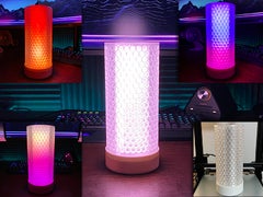
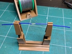
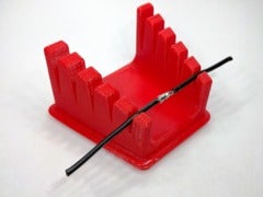
 Some of My Designs
Click an image below (opens in a new tab) or go to my designs page and see them all.
If you see some thing that you like  , please click the
  Like button and turn that heart red
  .
.