
Startup and connection sound is too loud ?
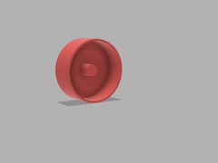
Here my „Buzzer Cap“ to reduce the loudness of the buzzer.
Simply put it on the buzzer.
A video how to install the cap you will find on YouTube (thanks to Lizard_Wizard):
https://youtu.be/qiJSN4i9X44
Startup and connection sound is too loud ?
Here my „Buzzer Cap“ to reduce the loudness of the buzzer.
Simply put it on the buzzer.
A video how to install the cap you will find on YouTube (thanks to Lizard_Wizard):
https://youtu.be/qiJSN4i9X44
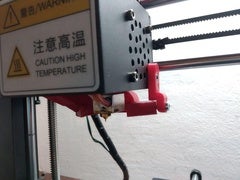
I made this Holder for my Anycubic Mega-S Part Fan Duct Half-Circle (Remix) from „SmashD“, because I had a little sagging Problem with my PLA Fan Duct and didn´t want to print a Hotend Cover. I drilled a hole, about 3mm, in the fan housing and screwed everything together.
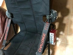
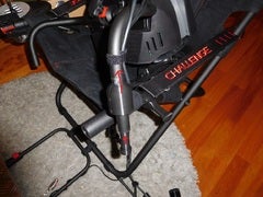
Sistema de Bodyshaker lowcost para nuestros Playseat Challenge. Probé a instalarlos en diferentes localizaciones y sin duda en esta posición es donde producen mayor vibración y mas sensaciones.
Como programa de pc yo uso SimShaker, que también es más económico que el Simvibe y funciona muy bien.
Basado en el montaje de:
https://www.thingiverse.com/thing:561762
https://www.thingiverse.com/thing:2613282
MATERIALES:
2 Bodyshaker 100w, 4 Ohmios, frecuencia 28 – 55 Hz
1 AMPLIFICADOR Kinter MA-180 (el conector de altavoces está al revés: izquierda es derecha y derecha es izquierda) Personalmente yo uso el amplificador con el BASS casi al máximo y el TREBLE casi al mínimo.
1 ADAPTADOR DE CORRIENTE 12v 5A:
Cables de conexión al pc o consola
Tornillos:
La abrazadera va cogida al tubo con tornillos M2,5×20 (tuve que calentar por debajo las tuercas con un soldador para colocarlas en su posición)
Entre la abrazadera y el plato use tornillos M3x16
Y entre el plato y los Bodyshaker usé M3x25
English:
System of Bodyshaker lowcost for our Playseat Challenge. I tried to install them in different locations and definitively in this position it is where they produce excellent vibration and sensations. The program of PC that I have is the SimShaker, which also is more economic than the Simvibe and works very well.
Based on the assembly of:
https://www.thingiverse.com/thing:561762
https://www.thingiverse.com/thing:2613282
MATERIALS:
2 Bodyshaker 100w, 4 Ohms, frequency 28 – 55 Hz
1 AMPLIFIER Kinter MA-180 (the connector of loudspeakers is wrong: left side is right and right it is left) Personally I use the amplifier with the BASS almost to the maximum and the TREBLE almost to the minimum.
1 ADAPTER OF CURRENT 12v 5A:
Plug wires to the PC or console
Screws: The clasper is taken to the pipe by screws M2,5×20 (I had to warm for below the nuts with a welder to place them in his position) Between the clasper and the plate uses screws M3x16 And between the plate and the Bodyshaker I used M3x25
I printed this at .2mm with PET-G. The design is quite sturdy so it should withstand all forces with PLA as well.
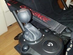
After printing the first step is to put two pieces of rubber inside the clamp, where it makes contact with the chair tube. After the support is mounted on the chair I used two leftover screws from my playseat challenge and mounted the gear shifter.
If anyone needs the source files I can share those too.
EDIT:
I UPDATED THE DESIGN TO BE A TIGHTER FIT AND EASIER TO INSTALL. THEY’RE SLIGHTLY DIFFERENT FROM THE ONE IN THE INSTALLATION PHOTOS, BUT THE PARTS INSTALL THE SAME WAY AS BEFORE.
These two parts are designed to remove the play in the steering bar of the Challenge racing rig, where it connects to the seat frame.
One part is a bushing that goes around the outside and one part is a plug that is a better fit inside the tube than the stock tube.
The bushing has a hole on the underside which can be used to lock it in place with M4 screws or set screws if it’s a loose fit. Assorted screws via my affiliate link at Bangood:
https://www.banggood.com/300Pcs-M4-M5-M6-Stainless-Steel-Hex-Socket-Cap-Head-Bolts-Screws-Assortment-p-1218506.html?p=HD240528697332015103
Check out my other Playseat Challenge accessories as well:
https://cults3d.com/en/3d-model/gadget/playseat-challenge-thrustmaster-th8-shifter-mount
https://cults3d.com/en/3d-model/gadget/playseat-challenge-headset-vr-hanger
Update
I realize now that I wasn’t very clear about which dice tower I was designing for, considering I marked both Lau85’s and BouncyMonkey’s towers as ‚remixed from.‘ To clarify, my original design was for BouncyMonkey’s ‚Yet Another Dice Tower.‘ I’ve since added a design that will fit Lau85’s ‚Another Dice Tower.‘
So:
Sorry for the slight confusion!
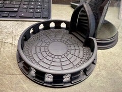
I wanted a tray to catch the dice as they came out of BouncyMonkey’s Yet Another Dice Tower and loved the style of Tray_v2 from Lau85’s Another dice tower, so I created a new tray merging the styles of both. The tolerances might be a tight between the base of the tower and the tray, but some light sanding will fix that.
Edit 7/1
Added a new version to fit the original ‚Another dice tower‘ by Lau85. I haven’t tested this for fit. Let me know in the comments if it works.
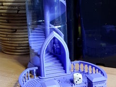
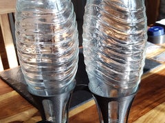
Here’s my take on a dice tower. I really liked the look of all those medieval towers, but also wanted to be able to watch the dice going down. So I designed my own.
This design uses a piece from a plastic soda bottle for the outer wall, diameter 87mm – length 170mm with a straight wall. I used a Dr.Pepper 1,5L bottle. To get the opening for the door, you can place the bottle on the base, then trace along the inside of the door using a pen or pencil. Then cut away the opening.
Note: If you have a bottle with a slightly different diameter, you can scale all the parts by X=d/87, with d diameter in mm. The required length, in mm, would be 170*X. For the 1,5L SmartWater bottle, that’s commonly found in the US, X would be 103.5%.
The little knight is something i liked for decoration in the window behind the entrance. It was sliced and scaled from the model by bs3 (https://www.thingiverse.com/thing:1239427). But it’s optional, you can leave it out or paint or put something else in there to personalise the tower. The measures of the window are width x height x depth:26x45x7mm.
As for printing, I gave all the parts steep angles, so I was hoping they would print without much support, but they still need some, particularly the staircase. It’s all easily removed though, I had no problem cleaning the parts.
Update: new Spiral.stl. The mesh is a lot cleaner now.
Update 21-11-2018: New Top_v2.stl. There where a lot of comments the outer rim came off after printing due to the small contacts in the brickwork. I’ve increased the wall thickness a bit and hope it’s resolved now. Please inform me if it’s still an issue. Also added a step to cover the alignment hole and improved the paving a bit as well.
Update 4-12-2018: Finally found the time to add a matching tray. It will fit on the tower without modification and can be nested for easy transportation. It should print without support if your printer can do some small bridges, but with will probably be safer. (I didn’t design the floral decals at the front of the pillars, they came from Bruxxus –https://www.thingiverse.com/thing:2168783– scaled to 12mm)
The file turned out quite big though, so I added another tray that’s more basic. It will fit on the tower just the same though.
Update 10-5-2019: New Tray_v2. There were comments on difficulties with printing the bannisters, so I’ve increased their thickness and hopefully that will make it better. Also included versions for low resolution and high resolution (small or big file).
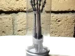
This is a remix for Terminator Arm replica“ by dazvette, modified a little bit in the base to avoid supports, and completed with a „Glass“ container, made of a Parmesan cheese empty PET bottle.
The 85 grams Kraft Parmesan cheese bottle fitted perfect to this 118 mm tall replica.
My own Version of a Crystal Bottle Stand. You can choose a single or a double Stand. I printed this with 3 Perimeters and that needs round about 120 Gramm of Filament. No Rafts and no support needed.
Enjoy!!
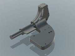
I couldn’t find a Logitech shifter mount on Thingiverse that satisfied me, so I made my own in Fusion 360. Note, I have only tested the right-hand version of this mount, however I expect the left-hand version will work fine. I just mirrored all of the components. There are 3 parts required for this print; the inside bracket, outside bracket and the surface to which you mount the shifter. The surface is designed for the Logitech G27 shifter, and I expect the other similar shifters. I only have the G27 to test.
Update 6/26/2019
I’ve confirmed that this works fine with the Thrustmaster TH8A shifter using the provided clamp. It’s secure enough, and positioned well enough, that I’m not going to bother making and reprinting a hard-mount plate for it. Much better shifter than the G27/G29/G920 variants by the way.
There were a few main goals for the utility of the mount:
The outside mount and surface are in 2 pieces for a couple reasons:
This was designed to be assembled with either M3 screws with 5.5mm nuts, or M4 screws and no nuts. I did not try this with M4 screws as I have a lot of M3’s around used for quadcopters.
The brackets mount to the tube with 30mm M3 screws and nuts inserted from outside to inside. Any longer and the screws will extend beyond the inside bracket, which is fine, but causes an exposed sharp surface. I also used washers under the screw head, but it’s probably not required. You can use slightly shorter screws if using M4’s. I did not need to use all of the screw holes. When looking from the outside bracket in, I used the top 2 on the far right, the bottom right, and top left. If using the bottom left, you’ll need to use an M4 screw, or a wood screw of the correct size, no more than 30mm. With the screws I used, it secures nicely to the tubing with no movement.
The surface slides onto the outside bracket and mostly locks into place. The outermost screw holes are countersunk as the shifter sits over top of them. That is the primary reason for the step-down, so there is enough material for both the surface and bracket. The inner holes do not side under the shifter, and I wanted to ensure plenty of strength where the surface and bracket meet. I’m not sure how well this part would hold up with M4 screws attaching the surface to the bracket, but I expect it would be fine.
The countersunk nuts are a tight fit on purpose. I just get them started by pressing them into their holes slightly, then use the screws to pull them into place. This essentially integrates them into the print so they won’t fall out when disassembling.
I printed this with red MatterHackers PLA Pro, with print settings as described in the ‚Print Settings‘ section. It is plenty strong with minimal flex. I don’t expect it will break easily without a straight up karate chop. I expect this would also print great in PETG. If printing in ABS, you may want to increase the size very slightly to ensure you can get the nuts into their recesses and so the brackets fit around the tubing. All of the files should import into your slicer in the orientations suggested below.
I printed this with the tubing cutout towards the print bed, using supports under the tubing cutout. This ensures the outside fillet is smooth.
I suggest printing this as it imports into your slicer with the base on the print bed to ensure strength where the bracket attaches to the surface. I used supports for the horizontal part of the tubing cutout until the angle reaches near 45 degrees. I also used supports in all of the holes, but it may not be necessary. Finally, I used supports in the nut countersinks.
I printed this with the top of the surface on the print bed. You could print it the other way, but you will need to support the surface-to-bracket cutout and then it may not fit together well. I only used supports for the countersink for the screws.
If you want to remix this, ie. to design a surface for a different shifter, you can download the files that Fusion 360 will export here:
https://a360.co/2v8bojh