
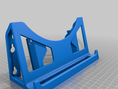
Headphone stand with optional mouse bungee, of „bottom_nut“ there are two versions, the second one has a small holder for the Hyperx Cloud II controller.
It is necessary print 2 „screw_16“.
Headphone stand with optional mouse bungee
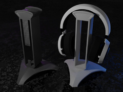
Headphone stand with optional mouse bungee, of „bottom_nut“ there are two versions, the second one has a small holder for the Hyperx Cloud II controller.
It is necessary print 2 „screw_16“.
Armas personalizadas con el rostro de personajes de películas de terror
Ich habe hier eine Halterung für die Amazon Blink mini WLAN Kamera entworfen. Die Halterung wird auf der linken Seite an den 2 oberen Schrauben befestigt. Die Kamera kann mit dem original Kugelkopf einfach eingeklipst werden.
UPDATE:
Nun ist die Halterung auch in Verbindung mit „LED-Holder V.1.5 – ANYCUBIC I3 MEGA
by Hiob“ zu gebrauchen.

The complete bundle for 3d printer & 3d models stl file
.
this is an updated version of my original design but with a working hinge 😉
BOM: (Bill Of Material)
2mm OD rod x 70mm L
Note: use the same rod to ream the hole in the hinges to the correct size
Accessories:
GAME: https://www.thingiverse.com/thing:2770543
PARA CORD GOODIES: https://www.thingiverse.com/thing:2774713
SEWING KIT: https://www.thingiverse.com/thing:2773357
SAW & BLADE: https://www.thingiverse.com/thing:2770206
CORD HOLDER: https://www.thingiverse.com/thing:2770523
ARROW HEADS: https://www.thingiverse.com/thing:2772221
BLADE SNAP CARDS: https://www.thingiverse.com/thing:2773170
SEWING AWL: https://www.thingiverse.com/thing:6215499
If you are interested in other prop firearms, Airsoft parts and designs do join our group on Matrix:
https://app.element.io/?pk_vid=f12152aac29bbc4a166549437941781a#/room/#GCI-General:matrix.org
!!!Note: I’m always open for suggestion and help on improving the design and proof of concept.
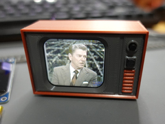
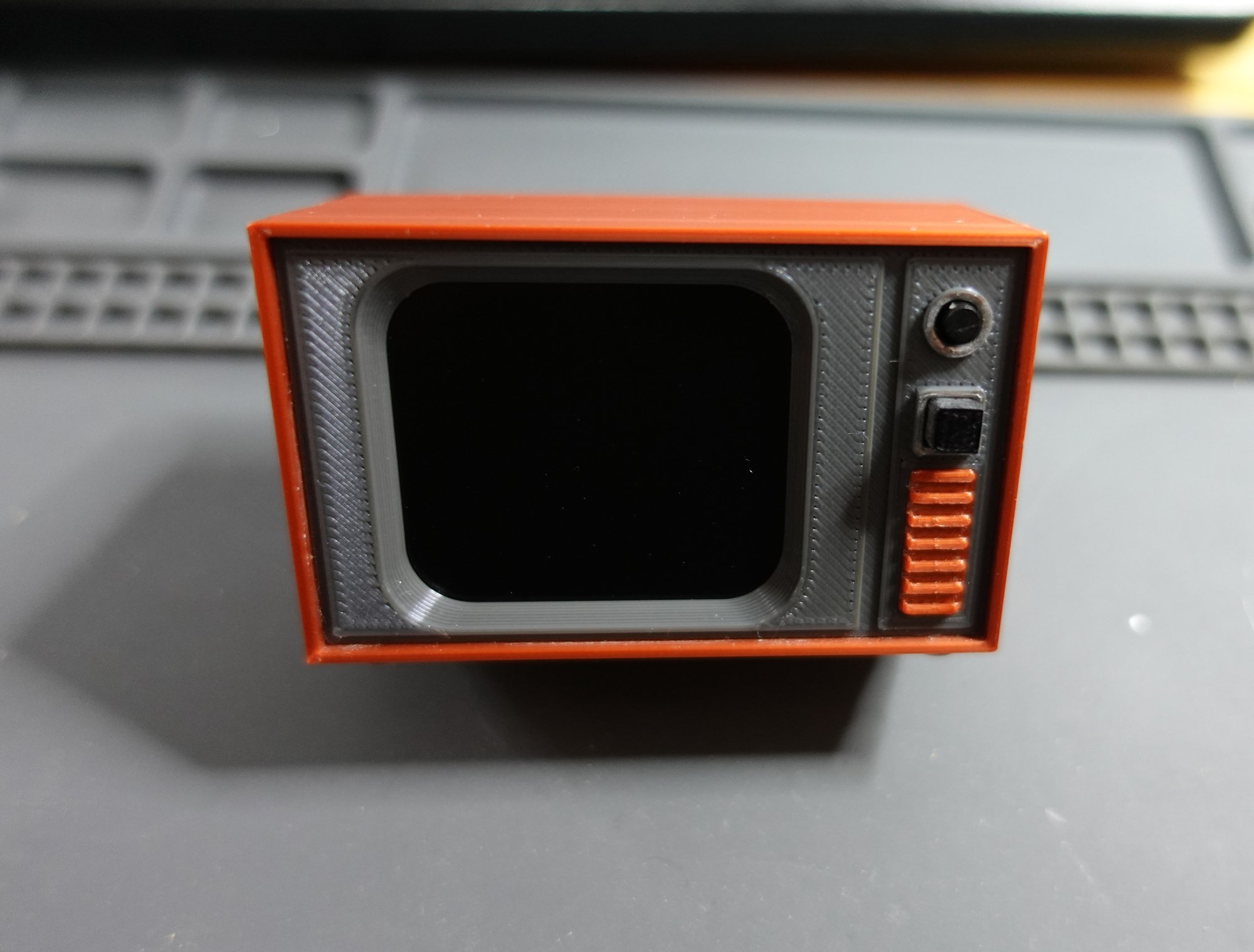
This Mini ESP32 TV project is remix of Moononournation’s Mini-Retro-TV Instructable. I wanted to try something with a PCB, and the slightly cheaper D1 mini ESP32. It has a front facing on/off button, and a single multi function button that can change movie clips forwards and backward and mute the TV if needed.
Notes My PCB Gerber files and STL’s are Public Domain. Everything else is whatever multitude of Licenses that other people assigned to their work. I take no responsibly for anything. Some adjustment of the front panel STL might be needed to completely centre the LCD display module with the screen bezel.
DON’T ASK ME FOR ANYTHING THAT IS NOT ALREADY LISTED HERE!
Supplies
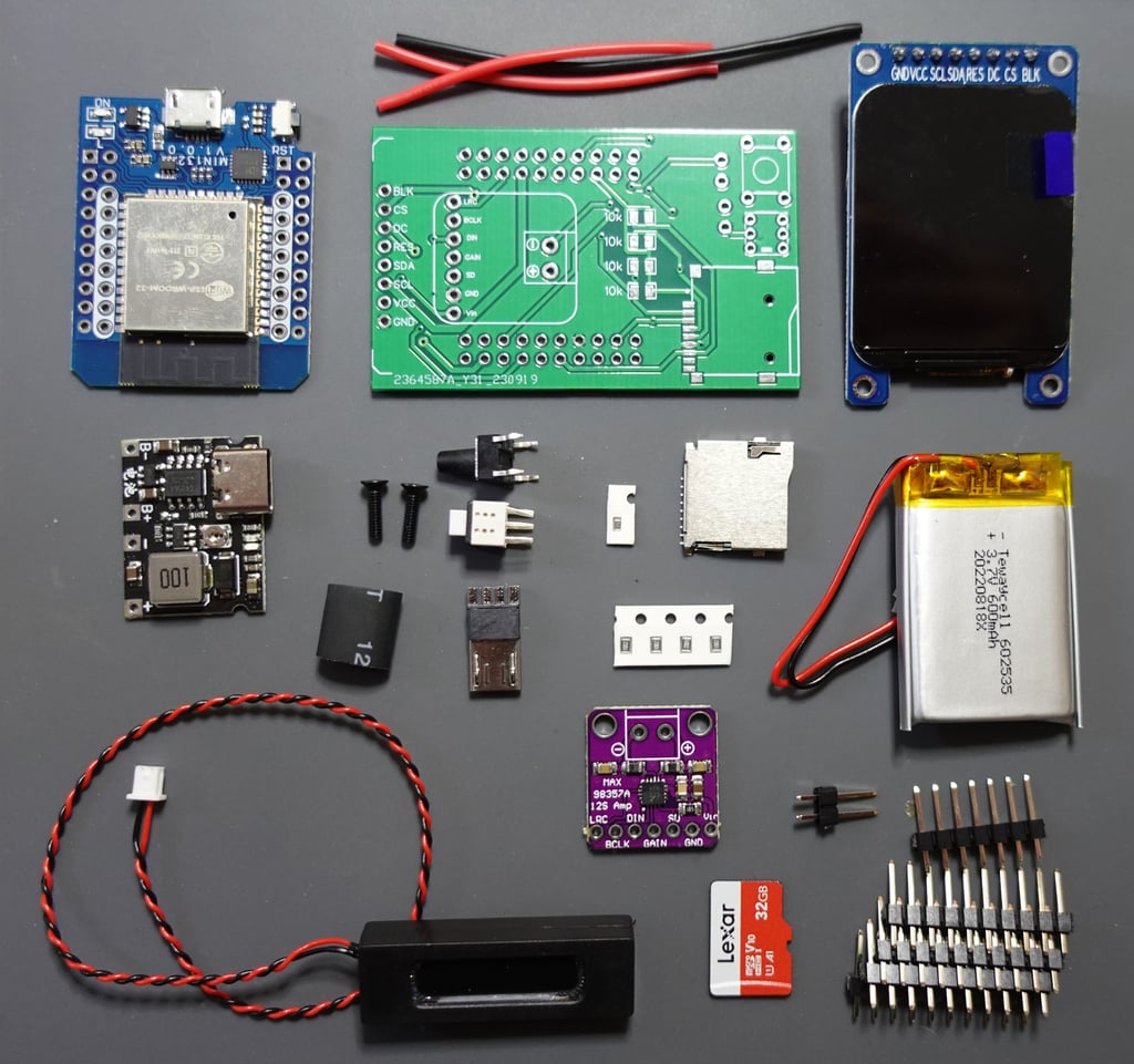
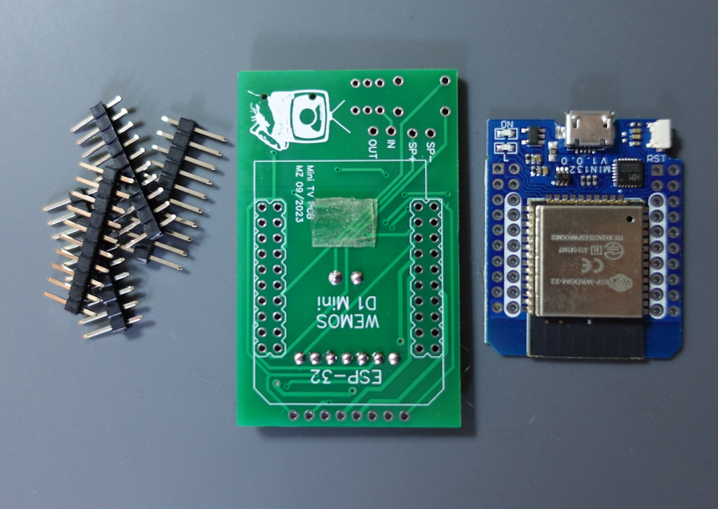
The PCB. This can be ordered from a PCB fabrication manufacturer Like JLBPCB : Gerber File Zip (Use default PCB board settings. 1.6mm thickness etc. Just upload the gerber zip and order)
1.69″ LCD display module: https://www.aliexpress.com/w/wholesale-1.69%252522-LCD-display-module.html
D1 mini ESP32: https://www.aliexpress.com/w/wholesale-D1-mini-ESP32.html
Max98357 I2S module: https://www.aliexpress.com/w/wholesale-Max98357-I2S-module.html
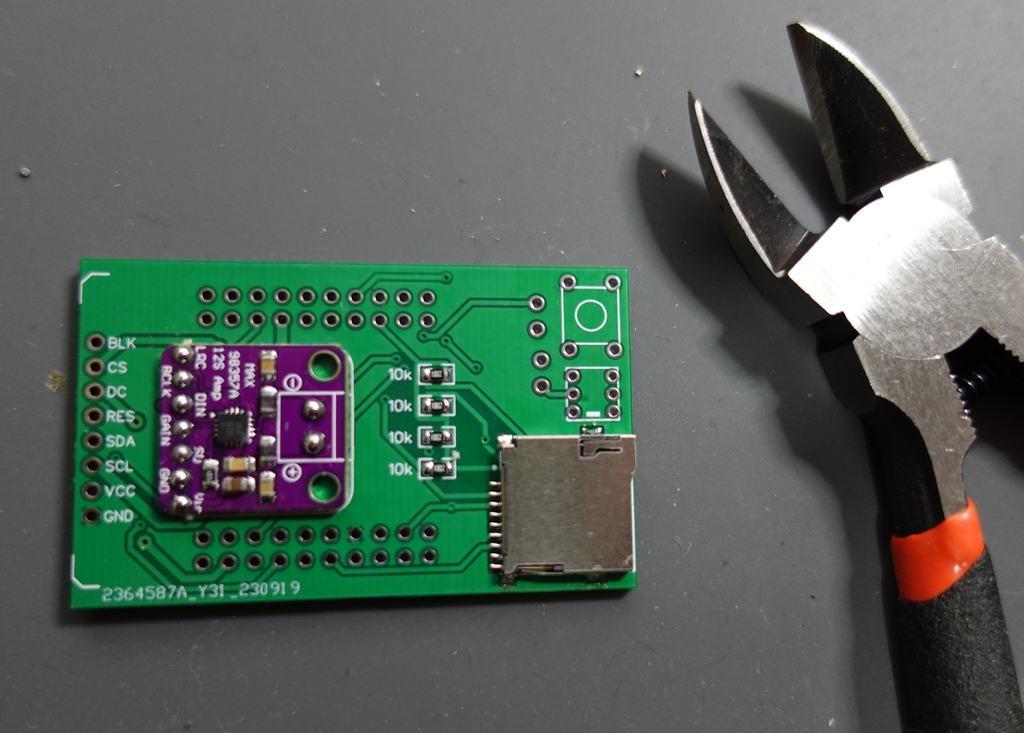
4 x 10k SMD resistors (size 0805) 1/8W: https://www.aliexpress.com/w/wholesale-10k-SMD-resistors-0805-1%252F8W.html
1 x 5.1k SMD resistors (size 0605): https://www.aliexpress.com/w/wholesale-5.1k-SMD-resistors-0603.html
9pin Micro SD card slot connector: https://www.aliexpress.com/w/wholesale–9pin-Micro-SD-card-slot-connectors.html
(The exact one used was this one: https://www.lcsc.com/product-detail/SD-Card-Connectors_G-Switch-GT-TF003-H0185-01_C5155563.html)
Battery Charger Boost Module TP4056: https://www.aliexpress.com/w/wholesale–Battery-Charger-Boost-Module-TP4056.html
1 x 5.8×5.8x7mm Tactile Push Button Latching 6 Pin: https://www.aliexpress.com/w/wholesale-5.8×5.8x7mm-Tactile-Push-Button-Latching.html (mine came from Amazon)
1 x 6x6mm 9.5mm(total height) Momentary Push Button Switch: https://www.aliexpress.com/w/wholesale-6x6mm-Momentary-Push-Button.html
Ghxamp Mini Speaker 8Ohm 1W 34.8mm11.2mm6.0mm: https://www.aliexpress.com/w/wholesale-Mini-Speaker-8Ohm-1W-34.8mm-11.2mm-6.0mm.html
2 x M2*8mm Black Hex Countersunk Screws (total length 8mm): https://www.aliexpress.com/w/wholesale-M2-8mm-Black-Hex-Countersunk-Screws.html
1x Lithium battery 602535 or 603035 : https://www.aliexpress.com/w/wholesale-Lithium-battery-602535.html
1 x Micro USB 4Pin Male Plug connector: https://www.aliexpress.com/w/wholesale-micro-USB–Male-4pin-USB-Connectors.html
2 x 40-pin Header Pins 2.54mm Male Single Row
A 32GB Micro SD Card (I used a Lexar 32GB from Amazon)
Black and Red Silicone Wire (around 26AWG )
Optional – Heat Shrink Tubing
Step 1: Charging Board
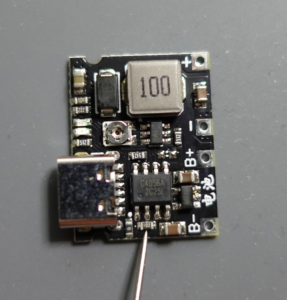
The charging (and voltage boost) board needs a resistor changed on it. This is the worst part of the whole project. My advice is to start with this. That way if you fail, you can just throw everything into the trash right from the get go.
By default the charging board outputs 1 Amp to the battery. This is too high for a 600mAh battery, and needs to be dropped down to 250mA by changing the resistor in the picture to a 5.1k 0603 resistor.
Use lots of light and a fine tip on your soldering iron. I also use a bit of flux paste. After you change the resistor, check your work with a loupe glass or some other magnifier.
Next, check the charging board is outputting 5v. Plug a 5v charger into the board and check the output. Adjust as needed using the output voltage potentiometer (the screw thing).
There are two solder pads marked „T“ on back of the charger board. If your battery has a protection circuit (most likely it does), you are supposed to solder the points marked T together.
Step 2: Program the ESP32
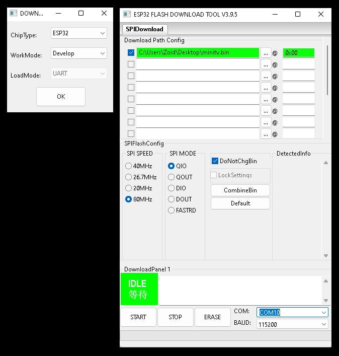
While you can program the D1 Mini ESP32 after it is attached to the PCB, it might mean shaving down a USB data cable. Save yourself the bother and program it now.
Download this Bin File Zip and unzip the bin file. Download the Espressif Flash Download Tool from https://www.espressif.com/en/support/download/other-tools. Unzip it. Plug the D1 Mini ESP32 into the computer’s USB port and run the flash_download_tool_3.9.5.exe.
Set ChipType to ESP32 and OK it.
Change the setting in the Flash Tool so that it reflects the settings in the above image. (you have to type in the 0x00)
Select your active COM port and click start. Once the upload has finished, unplug the ESP32… job done.
Step 3: Soldering 1
Now for the rest of the soldering. I switch to a medium solder tip, and use extra flux when needed.
Start with the 4 X 10 resistors, and then the Micro SD card holder.
Next is the Max98357 Audio Amp. Use flush cutters to get the pins cut down as low as possible. The biggest capacitor on the Amp should be higher than your solder joints. See above pictures.
Step 4: Soldering 2
Before attaching the D1 Mini, it’s a good idea to put some double sided tape on the PCB to hold things in place, and create a somewhat level surface. Solder all the pins, and remove the excess using flush cutters.
Next is the screen. We want this flat and parallel to the PCB. To aid in this, super glue the spacer provided in the STL’s to the PCB as seen in the picture 4. The highest capacitor on the Max98357 Audio Amp is now the same height as the spacer. So you have an unstable, but kinda flat surface. Use some Kapton tape to cover the components on the back of the screen and then solder it into place.
After soldering, use flush cutter to remove any excess from the screen pins. This is important since that is where the speaker is going to sit.
Next the buttons. Make sure they are pushed down and flush with the PCB before soldering. The latching on/off button should be attached as shown in picture 6. If you put it in the wrong way, it may not work.
Step 5: Soldering 3
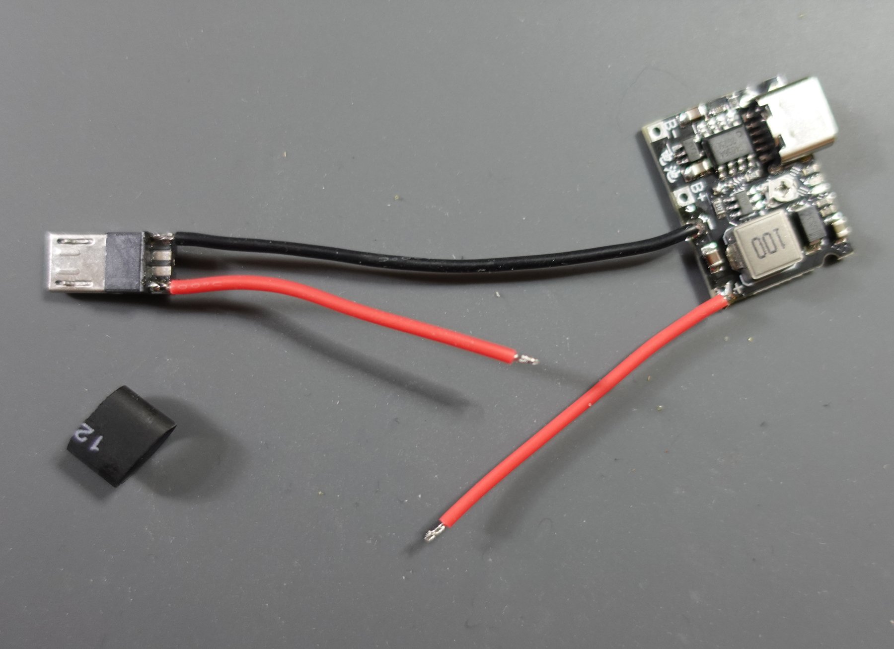
Next is the power and speaker.Solder the silicone wires as shown in the pictures. I like to use a little shrink wrap on the micro usb male connector.
Remove a little excess from the speaker cable and attach that to the PCB at the SP- and SP+ points.
Added the battery. Plug the male usb connector into the D1 mini ESP32, and if you have some movie files already on a micro SD card, you can test sound and vision. Without the micro SD card, it will just give: Error File System Mount Failed.
Step 6: The Case
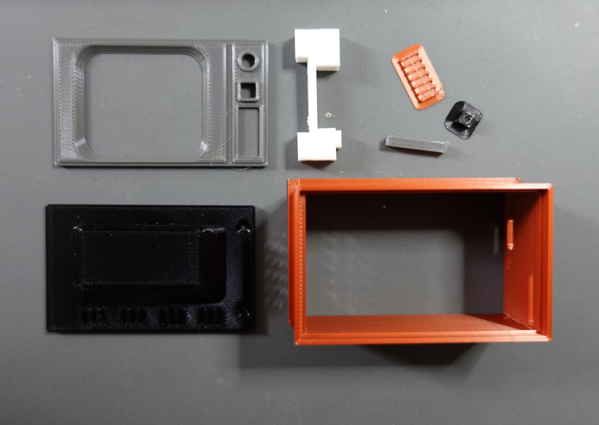
Download and 3d print the STL files for the Mini ESP32 TV project. These work for me, but people have different 3d printers and setups. I can only currently test these on an ancient Ender 3. Brown, Black and Grey PLA+ (The brown is actually „Copper“ silk). I use Eryone, but the brand doesn’t matter.
I used a small brim on some STL’s where there is not much surface area attaching them to the build plate.
I like to add some hot glue to the inside of the case at the small hole which acts as the charging light pass-through.Then remove the excess. This gives the charging light indication a sweet diffused look… bueno.
Next is the test fit. As you see in the picture 4, the screen bezel is a little off. It’s actually just 0.2mm too far to the right and 0.1mm too far down. Every single screen is fractionally different. I’ve made 8 mini TV‘ s and they all need slight adjustment in a CAD program like TinkerCad. Or just leave it as it is… up to you. In this case I made the adjustment in Tinkercad and reprinted the faceplate
Step 7: Case Assembly
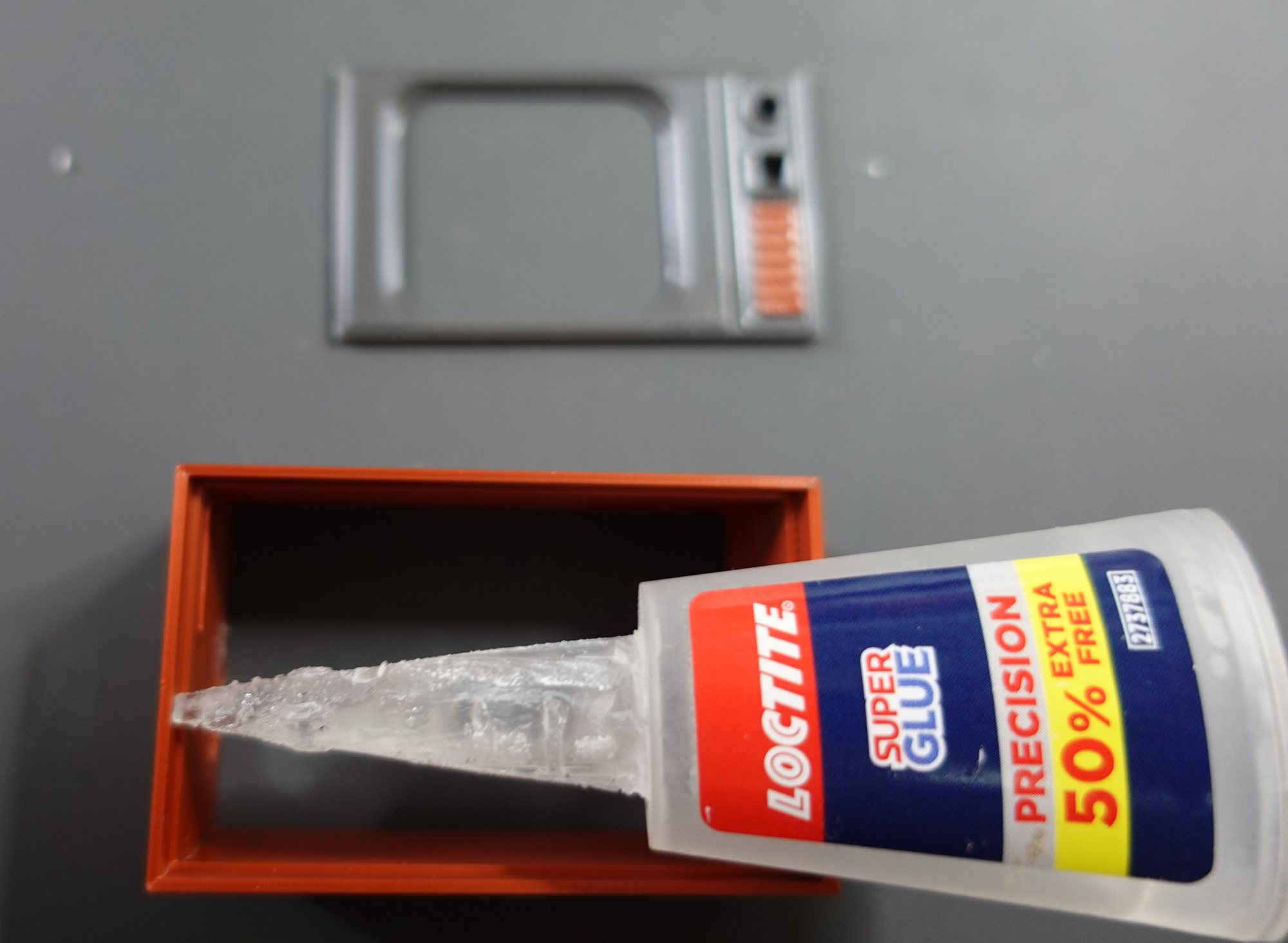
Once you are happy with the screen, superglue it to the TV body. There is a ridge going all the way around, so it’s pretty easy. Superglue the fake speaker grill part to the screen.
After the glue is dry, put the PCB into the case carefully. Make sure the micro SD card is not attached! Add the screw receiver part as shown in the pictures. Make sure it’s not sitting on top of any wires. Pop in the speaker, and sit the battery on the excess wires (this will keep it off the ESP32). Put the charging board through it’s USB C hole, and hold it in place with a charging cable.
Add the back and screw in the two hex screws. No need to over tighten them people. Remove the charge cable.
The final part is the ON / OFF button. This needs to have 4 sides sanded down so that it can move smoothly through the front panel. After sanding, use a very small amount of superglue on the flattest side, and attach it carefully to the power button on the PCB. DO NOT PRESS IT!!! Let it dry before pressing it otherwise the glue will wick down into the power button and ruin everything…. trust me on this.
Great Success! You can add some feet (or not). I used 6mm x 2.5mm clear 3M self adhesive rubber feet.
Step 8: Use
This project is 100% compatible with Moononournation’s Mini-Retro-TV code. You can use his code instead of the Bin File zip I supplied. The only thing that wont work is the channel change button (which is attached to GPIO pin 21). This additional code was done by somebody else, and I’m not releasing the source because reasons.
If you use the my bin file supplied in this Instructable the channel change button functions are the following :
1 press = move forward a movie. 2 presses = move back a movie. 3 presses = what number movie is playing. 1 long press = mute ON and OFF.
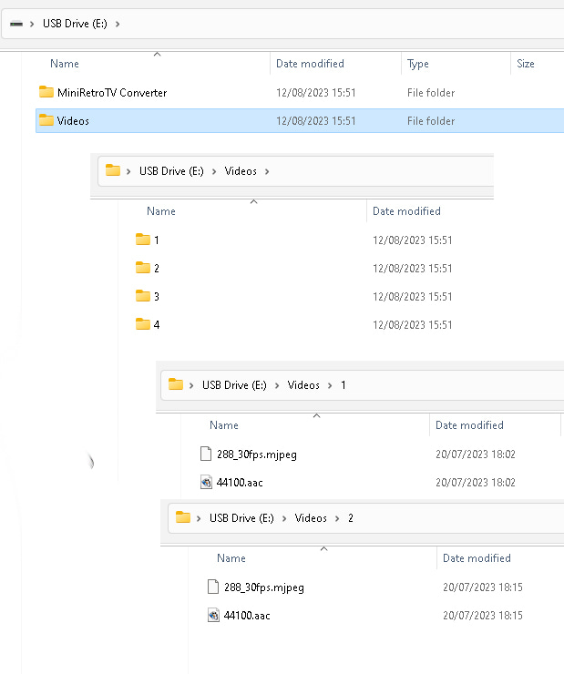
The directory structure of the micro SD card, and how to convert and add movie to it is explained in my YouTube video
It’s just a folder called Videos that contains sub folders numbered 1, 2, 3, 4 … etc (see picture 2 to get the idea). Easy.
MiniRetroTV Converter Software : Some software I wrote for downloading videos and putting them on the Mini TV.
Windows only software. Virustotal.com scanned.
THE
SOFTWARE IS PROVIDED „AS IS“, WITHOUT WARRANTY OF ANY KIND, EXPRESS OR
IMPLIED, INCLUDING BUT NOT LIMITED TO THE WARRANTIES OF MERCHANTABILITY,
FITNESS FOR A PARTICULAR PURPOSE AND NONINFRINGEMENT. IN NO EVENT SHALL
THE AUTHORS BE LIABLE FOR ANY CLAIM, DAMAGES OR OTHER LIABILITY,
WHETHER IN AN ACTION OF CONTRACT, TORT OR OTHERWISE, ARISING FROM, OUT
OF OR IN CONNECTION WITH THE SOFTWARE OR THE USE OR OTHER DEALINGS IN
THE SOFTWARE.
https://drive.google.com/file/d/1OU5hObSFPbrQ-10_yNw8dpauYMkQx0bq/view
Links to the PCB designs in EASYEDA:
https://easyeda.com/editor#id=d595c0524d494f1782ba7f6e70c5948f
KEIN VERKAUF!
Für:
ESP8266
NRF 24L01+ ext. Antenne
SSD1106 1,3″ oder SSD1306 0,96″ OLED Display
Gehäuse ist verschraubbar.
Dafür wird ein Messing Gewindeeinsatz (einschmelzen) für eine
M4 Schraube ( ca 2cm lang) benötigt.
Der Druck funktioniert auch ohne Stützmaterial.
Die Rückwand liegend drucken.
Das Oberteil auf die Displayseite legen und drucken.
Das Unterteil so wie es ist.
This is a combination of the Simple Steam Deck stand/wall mount by kwahoo and the Steam Deck Dock/Base for Anker 341 USB-C Hub (7-in-1) A8346 by SmashD.
It takes the Anker 341 USB C hub mounting solution from SmashD’s design and adds it to the back of kwahoo’s design, simple as that.
For reference if this will work for your hub, the small shelf that the USB C hub sits on is 117.5mm from end to end (the length of the hub) and 15.75mm wide (the thickness of the hub). The pitch angle of the Steam Deck holder (and the angle the hub holder was rotated to) is 15°.
Problem:
The shape and thickness of my new monitor does not really allow positioning the BenQ Screenbar on top of it. Furthermore the slightly curved display isn’t an ideal mix with the non-curved LED bar.
So I’ve created this adapter plate to place between monitor and screenbar. Enjoy. 🙂
Thanks to Platzhalter for a starting point for this model remix.
Just modified it slightly, added 4 slits so it can stretch a little better when there’s just half a mm missing, also added 4 spacers (or however those would be called) to lower the friction when you want to actually remove it again.
Printed in PETG (flexes better than PLA) and it’s fitting absolutely great, spot on!
To the original creator: great idea!